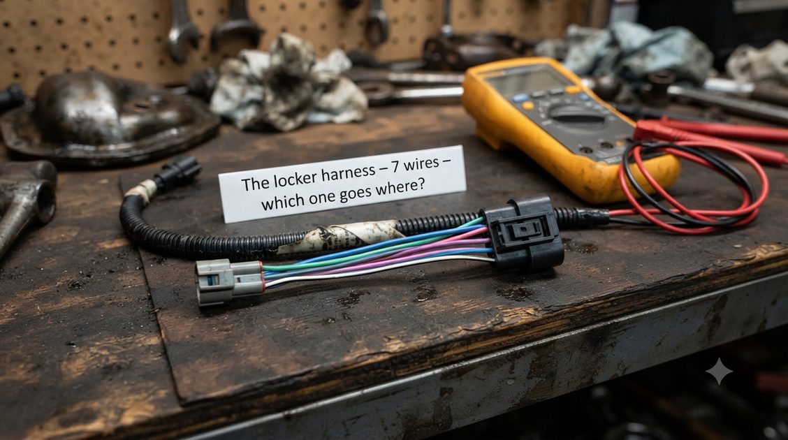
I'm in the middle of a project and I've hit a wall. Hoping someone here can help me out.
The situation: I'm retrofitting a factory rear e-locker into my 3rd Gen 4Runner that didn't come with one from the factory. I've got the axle, the locker motor, and the harness that plugs into the locker itself. I've got the factory dash switch. I've even got the little black ECU box that mounts in the driver's side kick panel — part number 89533-35070.
The problem: I need the wiring diagram for the ECU. Specifically, I need to know what each pin does and where the wires are supposed to go.
I have the 19-pin connector (Plug D29) sitting in the kick panel, and it has a bunch of wires coming out of it. But I don't know which wire goes to which pin, and I don't know which pins correspond to what function.
I've searched everywhere I can think of. I've been through the forums — I've found plenty of threads where people talk about doing this swap, but none of them have a clear pinout diagram for the 4Runner ECU itself. There's a lot of info for Tacomas and FZJ80s, but the 4Runner ECU seems to be different — part number 89533-35070 for the 4Runner vs. 89533-35060 for the Tacoma.
What I've Managed to Piece Together So Far
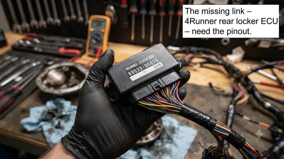
From scouring the forums and a few service manual snippets, here's what I've found:
Connector references: The ECU uses two connectors — F46 and F47. F46-4 is the ground (White-Black wire). F46-3 (IG) is ignition power (Red wire) — 11 to 14V with ignition ON.
The locker motor: There are two wires for the actuator motor — F46-8 (M1, Light Green) and F46-7 (M2, Blue). When you apply power to one and ground the other, the motor turns one way to lock. Reverse the polarity to unlock.
The limit switches: There are two limit switches that tell the ECU when the locker has reached full lock or full unlock. F47-6 (RLY1, Green) and F47-7 (RLY2, Pink) are for the actuator limit switch. F47-14 (RLP, Violet) is the lock detection switch.
The dash switch: F47-11 (R, Sky Blue) connects to the rear differential lock switch. There's also a Green-Orange wire (at D29 pin 10) that runs to the combo meter — I think this controls the dash indicator light.
What I'm missing:
A complete pinout for all 19 pins on the ECU connector
Which wires from the locker harness go to which pins on the ECU
Wire colors for the full harness (I know there are 7 wires from the locker plug — two plugs: a 2-wire plug for the detection switch and a 5-wire plug for the motor and limit switch)
Any relays or fuses in between that I need to account for
The exact factory wiring diagram from the 1996-2002 4Runner Electrical Wiring Diagram manual
What I'm Asking For
If anyone has access to the Factory Service Manual wiring diagram for the 3rd Gen 4Runner rear differential lock system — or if you've done this swap and have notes — I'd be incredibly grateful.
Specifically, I need:
A photo or scan of the EWD page showing the rear diff lock circuit with the ECU pinout
A list of what each pin on the 19-pin connector does
Wire colors and where they go (ECU pin → switch → locker motor → etc.)
Any known differences between the 4Runner and Tacoma ECU wiring
I'm also open to alternatives. If you've bypassed the ECU entirely and used a DPDT momentary switch to control the locker directly, I'd love to hear how you did it. I know you can wire the locker motor directly with a momentary switch and use LEDs for lock/unlock indicators. If I can't find the ECU pinout, that might be my Plan B.
What I've Already Tried
Searched every forum thread I could find
Looked through the Toyota 4Runner Technical Materials downloads
Checked the Terminals of ECU reference on various online resources
Tested the locker motor directly with 5.5V to confirm it works (pins 2 and 3 on the locker plug — it engages and disengages)
Ran an ohm meter through all 7 wires from the locker plug to the 4WD ECU to check for breaks
The motor works. The harness is intact. I just need to connect it to the ECU correctly — and I can't find a clear diagram anywhere.
If You Can Help
Please reply below with:
A photo/scan of the wiring diagram
A pinout list
Your notes from doing this swap
Or even just a pointer to where I can find the right manual
I've seen references to the 1996-2002 Toyota 4Runner Electrical Wiring Diagram manual and the 1998 4Runner wiring diagram. If anyone has a copy or knows where to find one, that would be gold.
Thank you in advance. I know this information is out there — it's just buried deep in the forums and hard to find in one place. If we can pull it together here, it'll help not just me, but everyone else who's trying to do this swap.



No comments yet — grab the first one.